For 2018 season made a swinging skeleton. The idea was not original and the inspiration was from a tutorial YouTube video posted by Bob Brozovich (https://www.youtube.com/watch?v=Ev_Y3vARSZw). Just modified his concept a little.
MATERIALS:
1" x 3" common board
1" x 2" common board
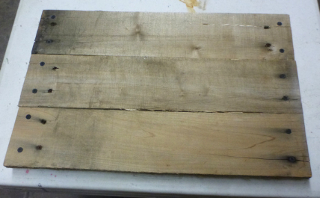
1" x 4" weather board (swing seat). I used wood from a top part of an old pallet.
1 1/4" Drywall screw
2 1/2" Drywall screw
1 Large I or C hook
1 pulley
Heavy gauge fishing line
3/8" natural fibers rope
Zip ties
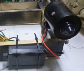
2- Speed 12VDC wiper motor. Purchased mine from Monster Guts.
PWM DC Motor Speed Controller. You can find at Monster Guts or Ebay.
14-Gauge ZMAX Galvanized Deck Joist Tie for 2x. Used to mount motor onto frame. Purchased from HomeDepot.
Posable Skeleton
Clamps
12DC 5amp power source. I used a car battery.
TOOLS:
Wire cutters & stripers
Saw
Philips screw driver
Electric Drill

Perron Halloween Productions copyright 2007-2019
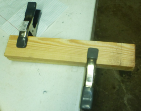
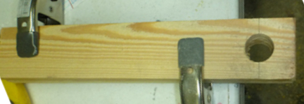
Clamp the two 1" x 3" x 15" frame side pieces together. Mark out the location for the 1 1/8" hole.

Drill the 1 1/8" hole.
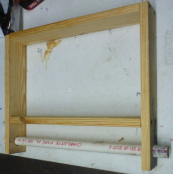
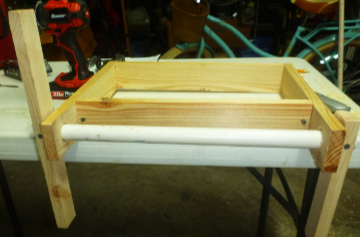
Assembly the frame together using 1 1/4" drywall screws
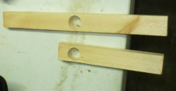
Cutout the two swing rope frame pieces and drill 1.0" hole. The photos don't show the angle cutout as shown in the drawing. You will want to cut them to help center the rope when added.
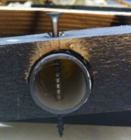
Center the PVC in the frame and mount the swing rope frame pieces onto the PVC with 2 1/2 drywall screws. Allow room so the pieces may move freely.
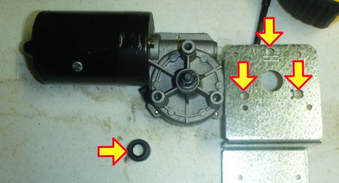
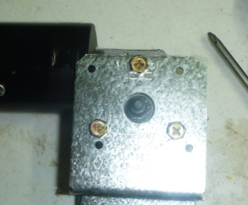
Removed the bushing that was on the wiper motor so it could fit through the large hole. Drilled through holes in the Galvanized Deck Joist Tie so the shaft was centered.
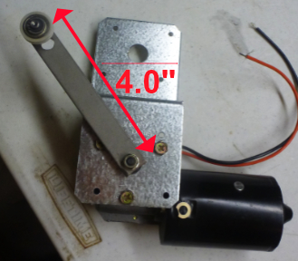
Mounted the motor onto the Joist Tie using the bolts that came with the wiper.
Used a piece of 1" x 4" x 1/8" metal for the arm. Attached a bearing pulley at one end. The wiper motor shaft has splines on it to bite into the metal.
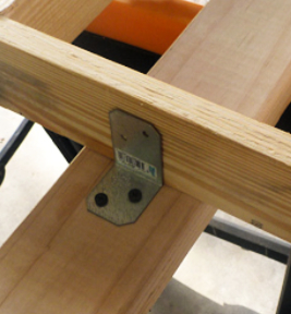
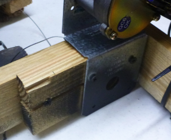
Mount the Deck Joist Tie onto the frame.
Installed an I hook in the top most part of the swing rope frame. Used 80lbs fishing line to attached the pulley onto the I hook. Length of the list was 9.0".
Attached the speed controller to the back of the frame with zip ties.
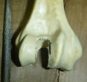
The pelvis bone as is would not allow the skeleton to sit properly.
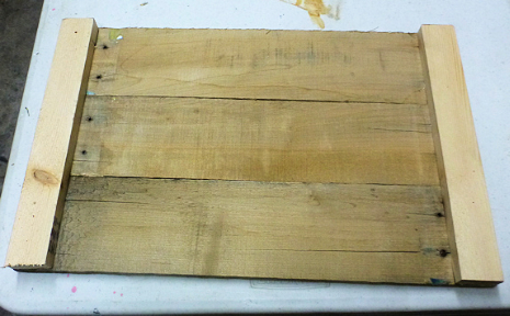
Above photos show the top and back of swing seat.
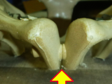
Front part of pelvis had to be cut too.
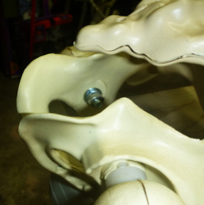
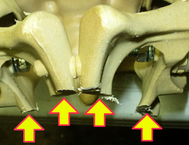
Parts of the back of the pelvis bone was cut away so the skeleton could sit flat.
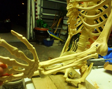
The range of the forearm movement was too low.
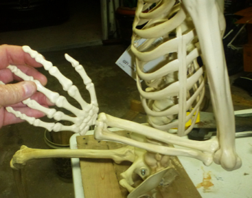
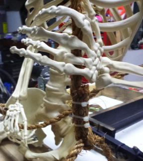
Used a round file to remove some of the material from the upper bone to allow more upward movement. This provides for a more realistic rope holding position.
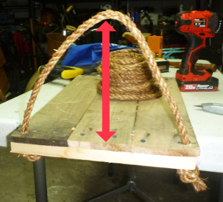
Drilled out holes at each end to secure the natural rope at a 7.0" height.
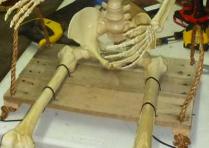
Attached the skeleton onto the swing seat by drilling out holds to pass the zip ties through.
Looped one end of rope around the rope that is attached to the swing seat and held it in place with zip ties. This enabled the position of the rope to be moved to adjust the tilt of the swing seat.
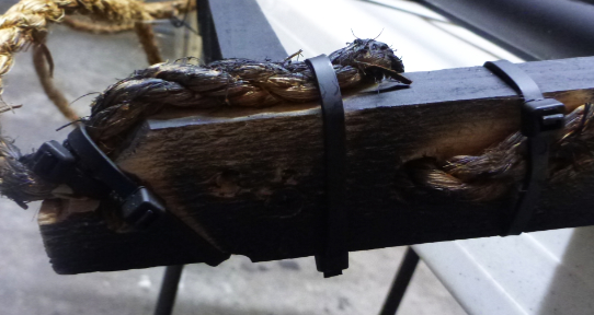
The other end of the rope was attached to the bottom of the rope swing frame. You can see the angle cut made in the end to help keep the rope centered.
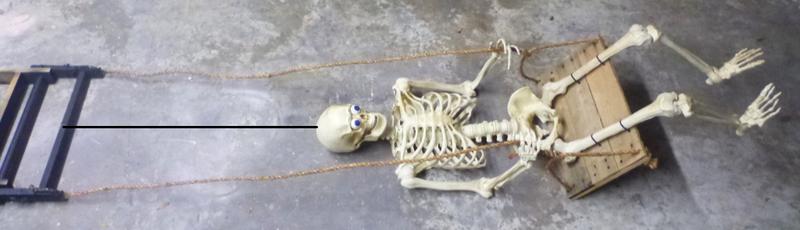
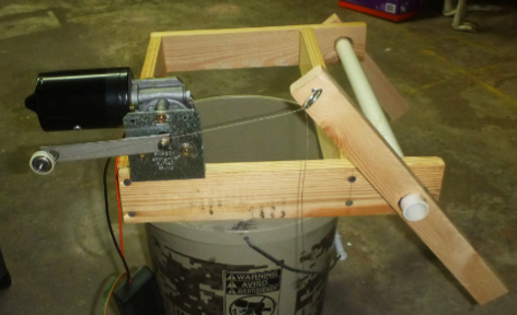
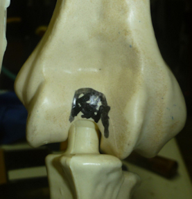
The distance of the rope from where it attaches to the frame to the swing seat is 57.0". The black line in the photo shows where you would attach the fishing line to keep the skeleton upright.
I attached the frame to a 2" x 4" using galvanized L-brackets

Below is a video that shows the skeleton swinging. You will need to adjust the speed control so you get the timing right to create a substained swinging motion.